
Step Up Transformer Model STEM Lab
Product Code : SCL-EI-12547
Introduce students to the engineering marvels of power transmission systems with the advanced Step Up Transformer Model STEM Lab Kit, masterfully manufactured by Educational Instrument India. Specially optimized for high-school physics classrooms, undergraduate engineering laboratories, and collaborative STEM environments, this premium educational model provides a transparent, safe, and robust vehicle to demonstrate how low-voltage alternating current (AC) is transformed into higher voltage via magnetic flux coupling.
The system features an accessible, exposed-core framework that allows students to look directly at the components hidden inside commercial utilities. The architecture centers around a heavy-duty, laminated silicon steel U-and-I core assembly engineered to mitigate parasitic core losses such as eddy currents and hysteresis. Mounted on this inductive pathway are two clearly identified insulated copper wire coils: a primary winding with a low turn count and a secondary winding boasting a significantly higher turn count. When a low-voltage alternating current is fed into the primary coil, it generates a continuously changing magnetic field. This dynamic magnetic flux routes through the laminated core matrix to link with the secondary winding, inducing an elevated AC voltage across the secondary terminals in strict compliance with Faraday's Law of Induction.
Designed with student interaction in mind, the non-conductive insulated baseboard features silk-screened circuit paths and explicit turn ratios. This eliminates confusion and empowers independent scientific inquiry, making it easier for educators to transform abstract calculations into tangible, hands-on discoveries.
Core Pedagogical and Technical Key Features:
Exposed Core Visualization: The open structural configuration allows students to interact directly with the core, clamp mechanisms, and interchangeable winding spools.
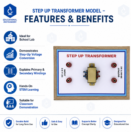
Safe Low-Voltage Input: Configured to deliver highly noticeable step-up results using safe laboratory power supply thresholds (e.g., 2V to 6V AC input), keeping output metrics well within safe touch boundaries.
High-Permeability Laminated Core: Constructed out of stacked silicon steel sheets to reflect authentic electrical grid engineering parameters by reducing thermal losses.
Integrated 4mm Safety Terminals: Engineered with premium, color-coded banana jack sockets to facilitate fast, clean, and reliable meter loops.
STEM Curriculum Mapping: Ideal for verifying transformers equations, exploring mutual inductance properties, understanding power line efficiencies, and computing turns ratios.
- Product Specifications
|
Parameter Matrix |
Technical Engineering Specification Details |
|
Brand Name |
Educational Instrument India |
|
Product Classification |
Electricity, Magnetism & Power Grids / STEM Lab Equipment |
|
Core Type |
Interlocking Laminated Silicon Steel Core (U & I Profile) with compression thumb screws |
|
Primary Winding Spool (Input) |
Heavy-gauge insulated copper wire wire-wrapped coil (approx. 100 to 200 turns) |
|
Secondary Winding Spool (Output) |
Fine-gauge insulated copper wire wire-wrapped coil with multiple extraction taps (approx. 400 to 800 turns) |
|
Maximum Input Threshold |
6V to 12V AC (Alternating Current) strictly supplied via an external low-voltage lab transformer |
|
Connection Interfaces |
4mm Insulated Safety Banana Socket Posts (Color-Coded Red & Black) |
|
Base Board Platform |
Rigid, high-dielectric insulated non-conductive compound with pre-printed schematic notation |
|
Dimensions (L x W x H) |
Approx. 210 mm x 140 mm x 115 mm |
|
Net Apparatus Weight |
Approx. 1.90 kg (Heavy base minimizes movement during lab adjustments) |
- How to Use the Step Up Transformer Model
To ensure precise scientific readings and optimal classroom safety, conduct all laboratory experiments in accordance with the following structured sequence:
CRITICAL SAFETY DIRECTIVE: Never link this open educational apparatus to a high-voltage household wall terminal or mains circuit. It must be powered solely through a regulated low-voltage AC laboratory power supply unit. Keep initial inputs low (e.g., 2V to 4V AC) to maintain a completely safe environment.
Assembling the Magnetic Core: Set the model on a flat table. Verify that the U-and-I core blocks are aligned perfectly flush against one another. Firmly lock the thumb-screws down; any air gap in the steel line will drastically reduce your voltage transformation efficiency.
Wiring the Primary (Input) Circuit:
Turn OFF your variable lab AC power unit and roll its knob down to 0V.
Connect two banana cables from the low-voltage AC outputs to the terminals marked Primary Winding (Fewer Turns).
Connect a digital AC voltmeter in parallel across these input ports to track your baseline primary voltage .
Wiring the Secondary (Output) Circuit:
Connect a second digital AC voltmeter across the terminals marked Secondary Winding (More Turns) to track the stepped-up output voltage.
For safety, ensure the voltmeter scale is set to at least 50V AC to catch the step-up response cleanly.
Powering On and Mathematical Verification:
Turn on your bench power supply and gently dial up the input to 3V AC or 4V AC.
Observe both readouts simultaneously. Note that the output voltage has scaled up significantly compared to the input .
Instruct students to cross-examine their physical results against the classic Transformer Equation:
Where match the turn values printed on the coil spools.
System Shutdown: Always dial the input power back to zero and power off the bench supply before changing any wire configurations.
- Frequently Asked Questions (FAQs)
Q1: Can this Step Up Transformer model work if I plug it into a standard DC battery?
A: No. Transformers require a continuously fluctuating magnetic field to induce an electrical current in a neighboring coil (via mutual induction). Direct Current (DC) from a battery produces a static, uniform magnetic field, which yields zero voltage generation in the secondary coil after the brief initial connection spike. Attempting to run DC into the primary winding for prolonged periods will simply overheat the copper wire.
Q2: If this is a step-up model, is there a risk of creating dangerously high voltages?
A: When used as directed with standard lab inputs (2V to 6V AC), the step-up output typically falls within a completely safe range of 12V to 36V AC. Educational Instrument India explicitly engineers the turn ratios for this model to prevent high-voltage hazards during standard school demonstrations. However, users must always follow the strict low-voltage input restrictions detailed in the manual.
Q3: Why is the core made from separate laminated sheets instead of a solid chunk of iron?
A: A solid iron core sitting inside an alternating magnetic field will develop strong swirling internal currents known as eddy currents. These parasitic loops convert massive amounts of electrical energy directly into waste heat, destroying efficiency. Stacking thin, insulated laminated silicon steel sheets breaks up these current paths, keeping the core cool and highly efficient.
Q4: Can we feed an AC signal into the secondary side to turn this into a step-down unit?
A: Theoretically, transformer actions are fully reversible; applying a safe voltage to the side with more turns would step the voltage down on the side with fewer turns. However, to keep classroom procedures uniform and prevent any accidental reversal mistakes that could cause unexpected step-up surges, it is highly recommended to use this model strictly as labeled.
.png)
.png)

.png)

.png)

