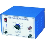
Quick Answer: This Transistor Characteristics Apparatus plots the V-I curves of NPN and PNP transistors in common emitter (CE) and common base (CB) configurations. It has IC-regulated variable supplies of 0–1V DC for the base and 0–10V DC for the collector, read on four analog meters.
Last updated: October 2026
Key Features
Tests NPN and PNP transistors in CE and CB configurations
IC-regulated variable supplies: 0–1V DC (base/input) and 0–10V DC (collector/output)
Two analog voltmeters, 0–1.5V and 0–10V
Two analog ammeters, 0–50µA (base) and 0–10mA (collector)
Mild steel (MS) enclosure with powder coating
Technical Specifications
Specification
Value
Configurations
NPN/PNP in CE and CB
Base supply
IC-regulated, 0–1V DC variable
Collector supply
IC-regulated, 0–10V DC variable
Voltmeters
Two analog: 0–1.5V and 0–10V
Ammeters
Two analog: 0–50µA (base) and 0–10mA (collector)
Enclosure
Mild steel (MS), powder coated
Dimensions
250mm x 350mm x 150mm (approximate)
About This Product
With four meters on the panel, students vary the base and collector bias and record the readings needed for input and output curves. Repeating the tests in common emitter and common base arrangements lets them compare the two configurations and study junction bias.
Frequently Asked Questions
Which configurations does this Transistor Characteristics Apparatus support?
NPN and PNP transistors can be tested in common emitter (CE) and common base (CB) configurations.



.png)

.png)